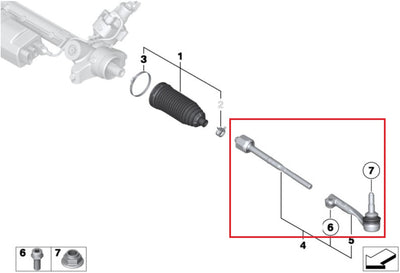
VERKLINE WAS-442 Fully adjustable wishbone kit - BMW F8x M2 / M3 / M4 - track package - stage 1 - product gallery

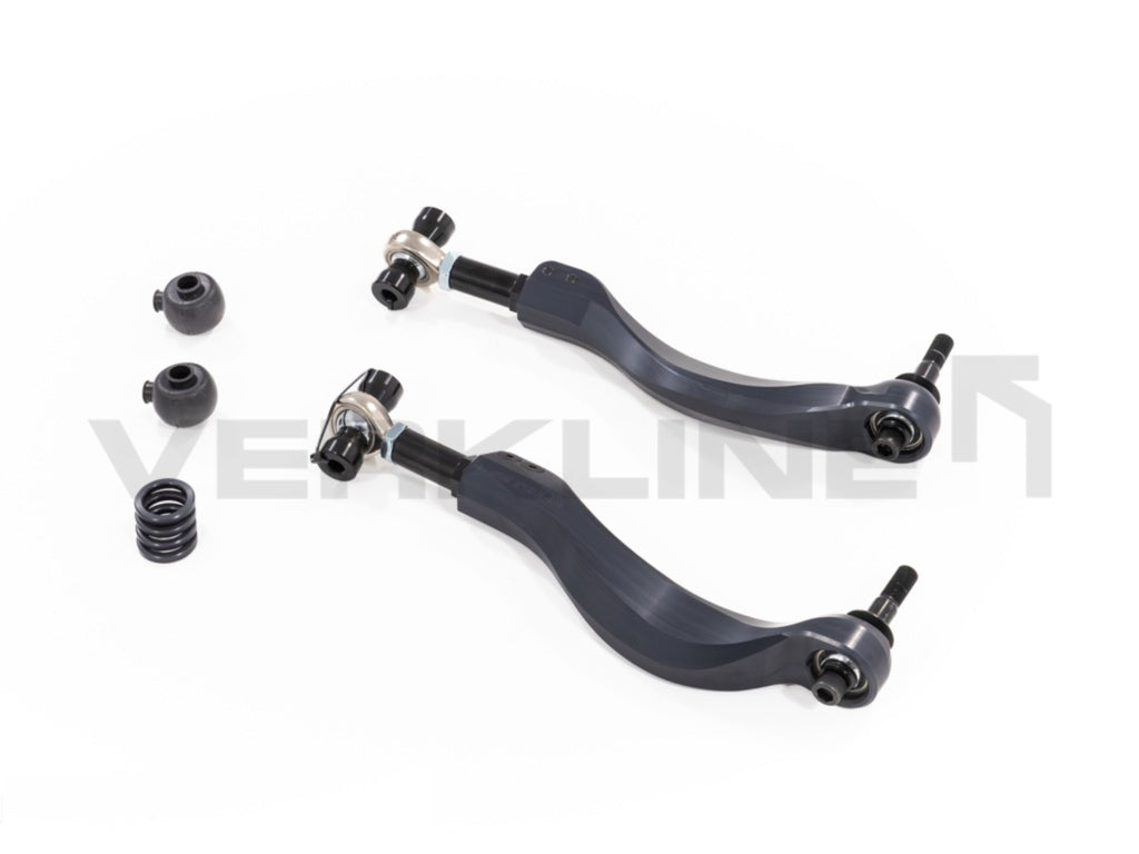
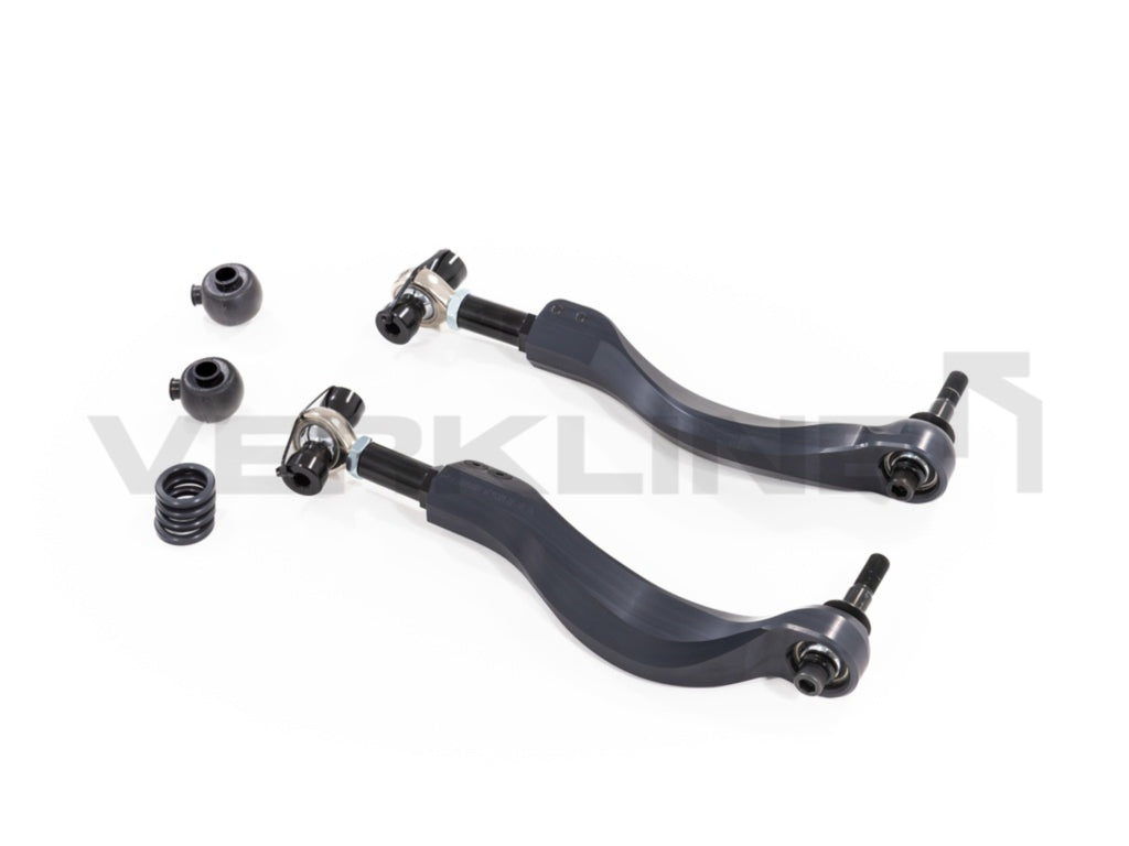
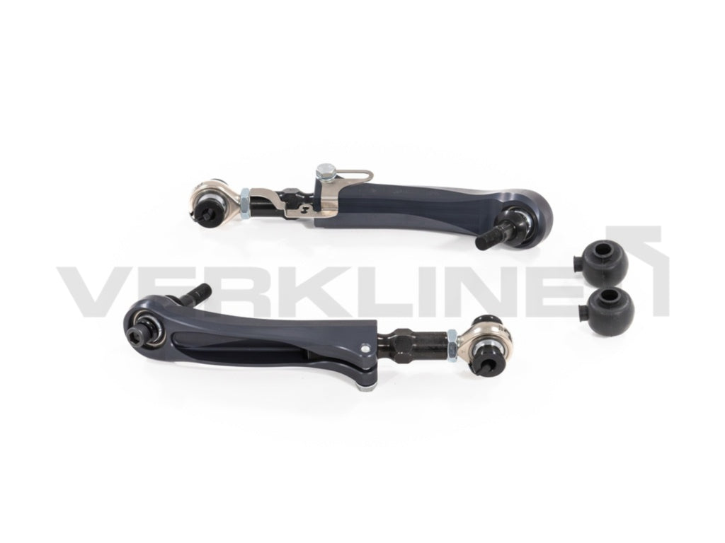
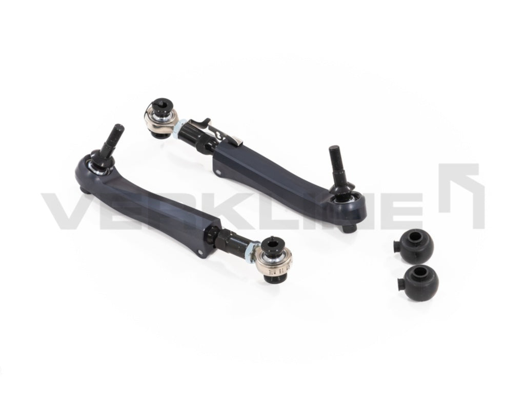
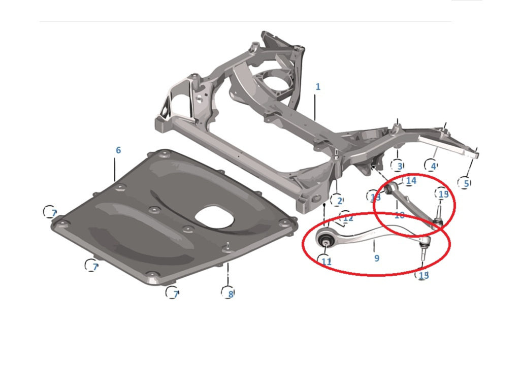
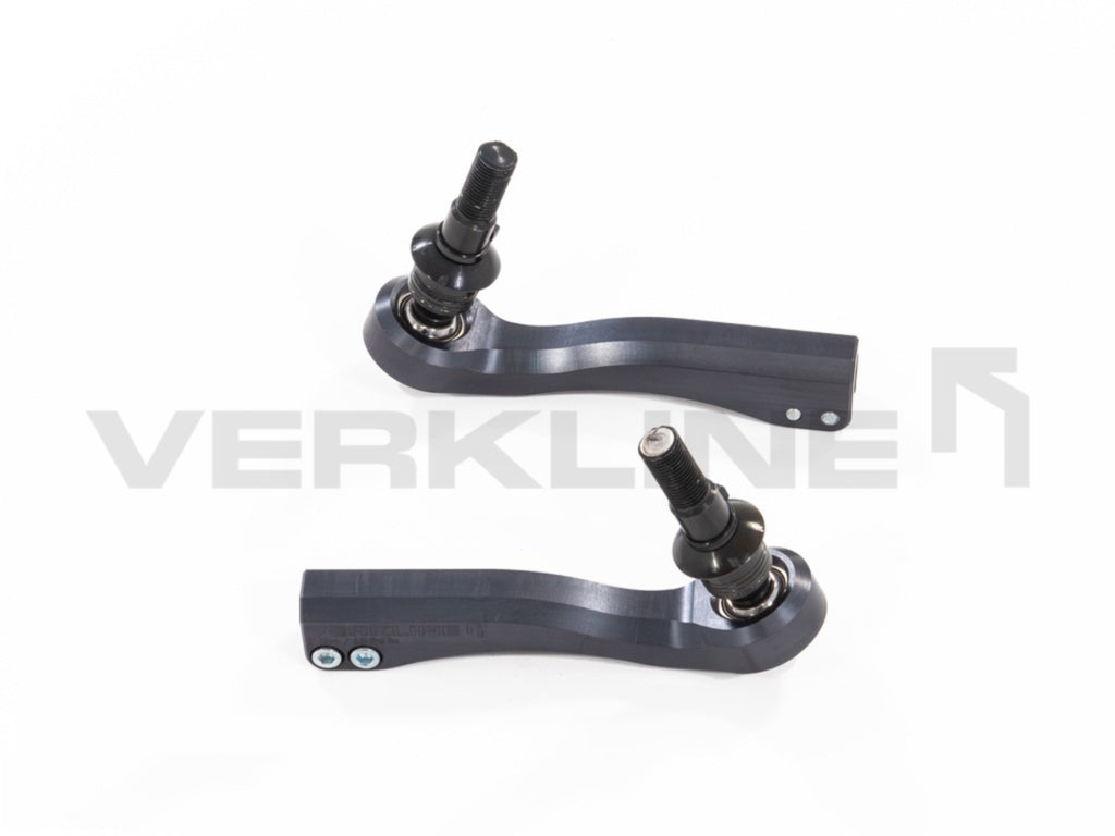
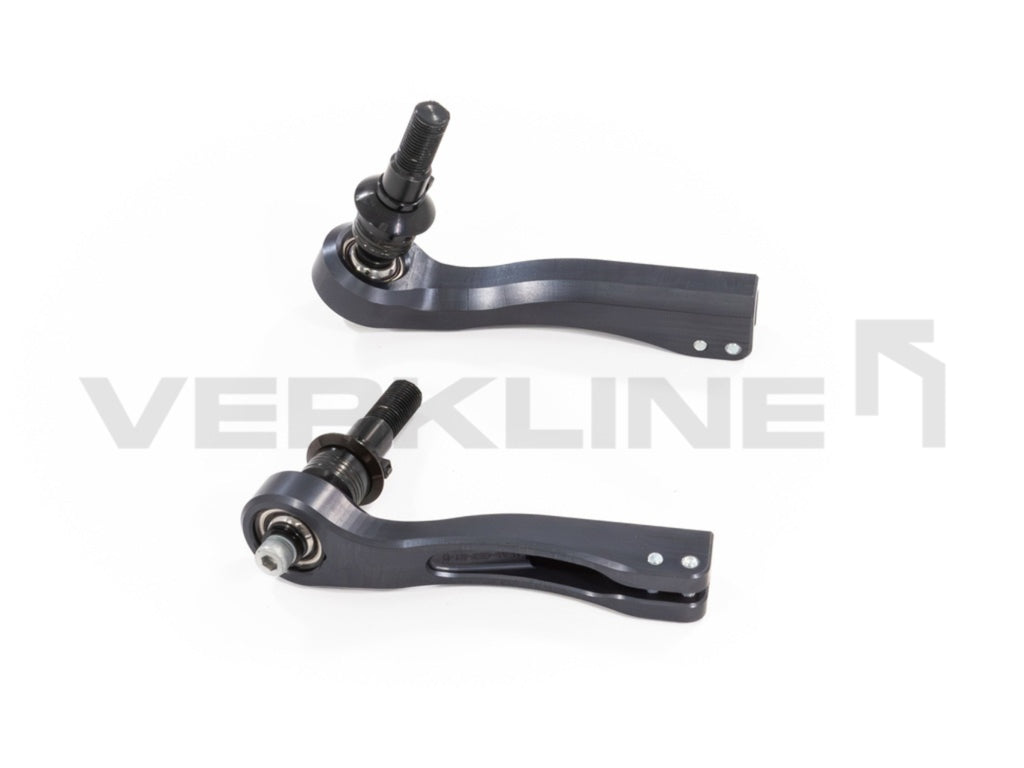
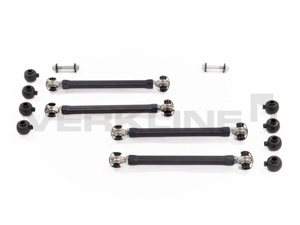
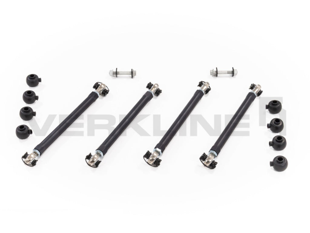
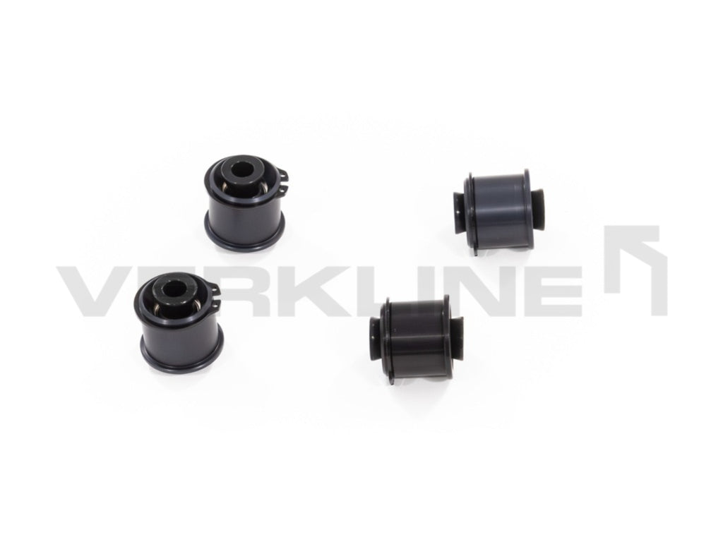
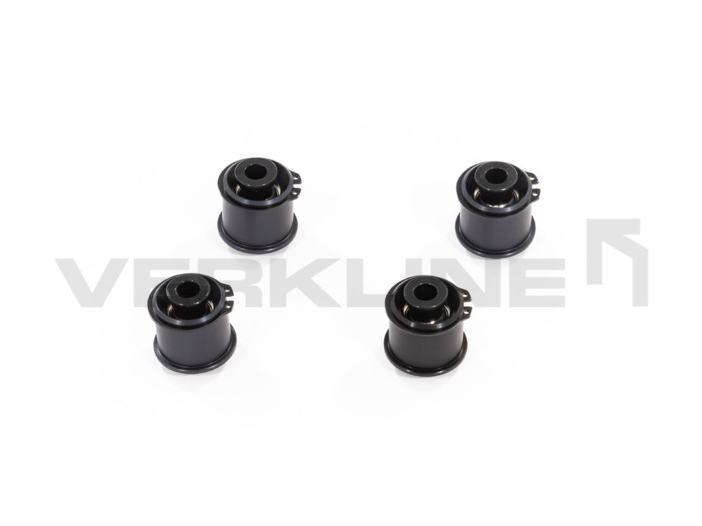
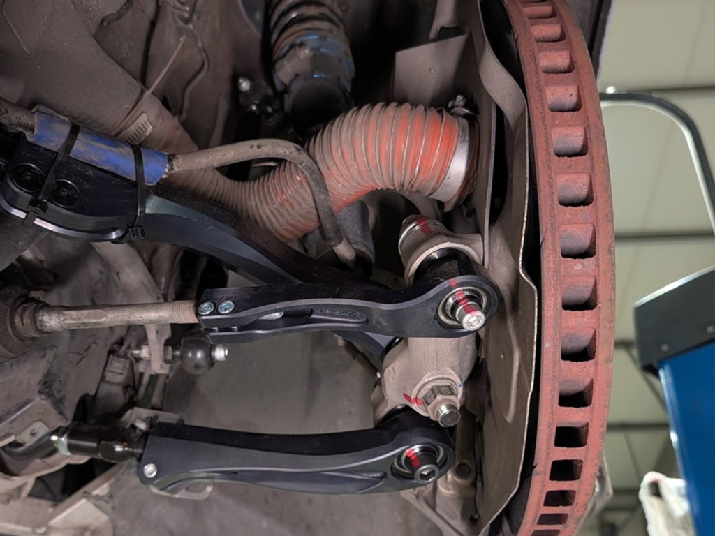
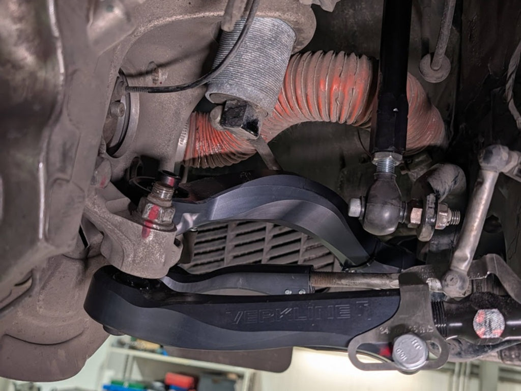
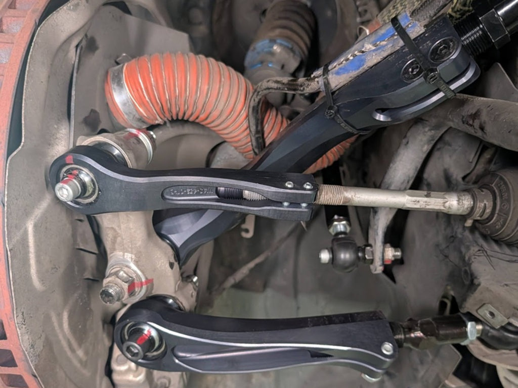
Fully adjustable wishbone kit - BMW F8x M2 / M3 / M4 - track package - stage 1
🎧 Audio description
Listen to the full product description
VERKLINE Fully Adjustable Wishbone Kit - Track Package - Stage 1
BMW M2 F87 / M3 F80 / M4 F82 - Complete kinematics & geometry correction system
The VERKLINE WAS-442 is a complete 22-piece fully adjustable wishbone kit for BMW M2 F87 (2015-2021), M3 F80 (2014-2018) and M4 F82 (2014-2020). It is the only F8x suspension kit engineered front and rear simultaneously in a single shared CAD model. Camber adjusts 2 to 5 degrees and caster adjusts 6 to 10 degrees, fully independently. All control arms are CNC-machined from AW-6082 T6 aluminium billet with 42CrMo4+QT alloy steel pins; every pivot uses an EU-manufactured Getecno MTE sealed motorsport spherical bearing with an additional external dust boot. Every load-bearing component was validated through FEA across 28 load scenarios before production. The WAS-442 is the arm-level stage of a complete kinematic ecosystem: Stage 1 (this kit - all front and rear arms) combined with Stage 2 (rear tubular subframe + CNC-machined front uprights) is the only solution on the market that covers every adjustable parameter in F8x geometry. Arms-only kits from other manufacturers can adjust what the factory already allowed - they cannot move the chassis pickup points. The kit ships with printed Fast Road and Track setup documents developed specifically for the F8x chassis.
Jump to: F8x problem · Highlights · What's included · Fitment & compatibility · Engineering · Stage 1 + Stage 2 ecosystem · Setup docs · Who it's for · FAQ · Specifications
The F8x Problem - What BMW didn't fix from the factory
The F8x M-chassis is one of the finest platforms ever built. But the factory geometry reflects road-car compromises that become real handling problems the moment you lower the car or take it to a track.
VERKLINE Stage 1 addresses all four of these problems simultaneously - not as individual part fixes, but as a coordinated kinematic system. Arms alone cannot reach 100% of F8x geometry: chassis pickup points, roll centre and anti-dive geometry are controlled by the subframe and uprights themselves. The complete answer is Stage 1 (all arms) plus Stage 2 (tubular subframe + CNC uprights). Arms-only kits are a significant step forward - not a complete one.
Product Highlights
The only 22-piece system that replaces the entire kinematic chain on both axles - designed together in a single shared CAD model. Every other manufacturer for the F8x offers either a front kit or a rear kit. VERKLINE is the only manufacturer that engineered both axles simultaneously, so clearances, bearing axes and adjustment ranges are guaranteed to work together by design. While others offer partial solutions, VERKLINE delivers a complete overhaul - all control arms, tie rods, drop links and inserts - eliminating 100% of rubber compliance and fully correcting geometry in one coherent system. The WAS-442 is also the arm-level stage of a complete ecosystem that continues with Stage 2 (rear tubular subframe + CNC front uprights) - together they cover every adjustable parameter in F8x geometry, not just the ones the factory already exposed.
Caster arm: ±22 mm adjustment range. Camber arm: ±25.5 mm, unlocking 2°-5° of camber and 6°-10° of caster - independently of each other. Because camber is adjusted via the lower wishbone rather than a top mount, adding negative camber simultaneously moves the wheel outward in the arch, widening the track. A wider track reduces lateral load transfer under cornering - meaning more grip from each tyre, not just more camber. Camber plates cannot achieve this: they tilt the wheel inward at the top without moving it outward at the bottom. The camber arm is rated to 23.2 kN peak load - structural data no competitor publishes. Every bearing operates within a verified ±25° articulation range across the full suspension travel. Steel components use 42CrMo4+QT alloy steel, quenched and tempered to over 750 MPa yield strength - exceeding the chromoly used by most competitors.
Every pivot uses an EU-manufactured Getecno MTE sealed spherical bearing - the top tier in the Rodobal (Italy) catalogue, above six lower series. Bearing body: 42CrMo4 quenched and tempered steel (same grade as our pivot pins). Race: AISI 316Ti stainless steel for corrosion resistance in salted-road climates. Ball: 100Cr6 hardened, ground, chrome-plated. Anti-friction: PTFE integrated into a bronze wire mesh matrix, not a surface liner. Preloaded zero-clearance coupling means no play develops over seasons. DIN 648K compliant. Static radial load 42 kN per bearing (RM 12 MTE series). Self-lubricating - no grease, no maintenance, no re-shimming. A PTFE-lined rod end develops play as the liner wears; a sealed preloaded MTE bearing behaves the same in month 1 and month 24.
Every moving joint on the WAS-442 is protected by three independent barriers against dirt, road salt, brake dust and water. Layer 1: the bearing itself is a sealed housing - the PTFE-on-bronze-mesh matrix is enclosed, not exposed. Layer 2: the arm geometry closes over the bearing so contaminants cannot reach the pivot from the arm body. Layer 3: every pivot ships with an external rubber dust boot factory-fitted at VERKLINE before packaging. Open or lightly-shielded rod ends - common across arms-only competitors - develop noise and play within a single season in climates with road salt and brake dust exposure. Sealed and boot-protected joints do not.
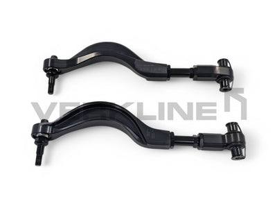
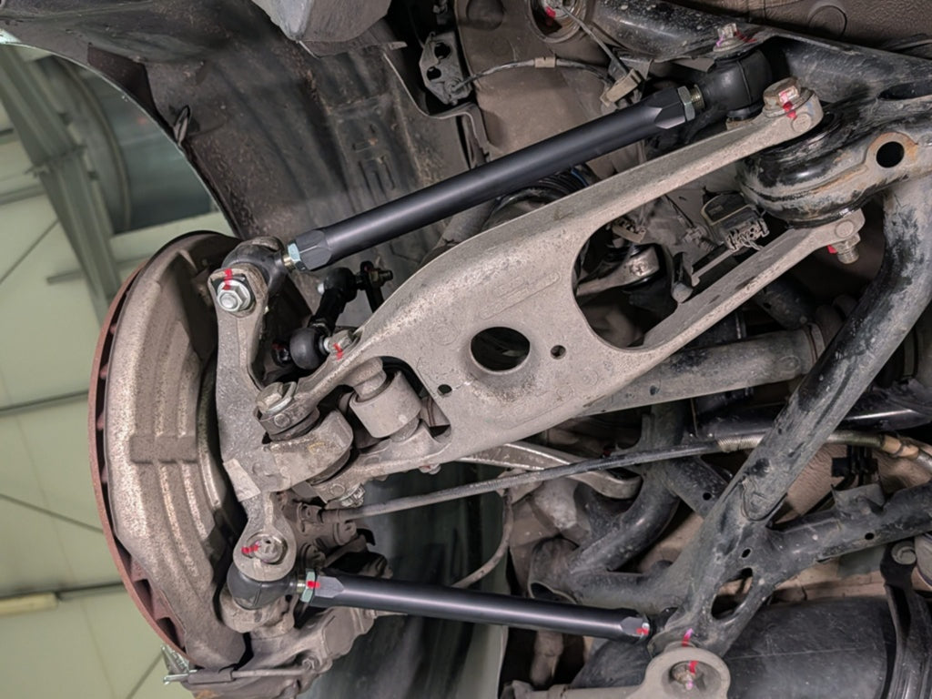
We engineered the only CNC-milled Caster Arm on the market to eliminate the risks of competitor straight-rod designs. Our unique geometry provides essential clearance to prevent tie-rod collisions and actively tilts the bearing housing to optimize articulation, ensuring zero binding even at extreme steering angles.
Every component was subjected to FEA (Finite Element Analysis) across 28 extreme load scenarios - including violent curb strikes, combined cornering and braking G-forces, and jump landing loads - before a single part went into production. This is the same validation methodology applied in professional motorsport engineering. The result is structural integrity that far exceeds OEM standards and gives you the certainty that nothing will crack or bend at the limit, a level of pre-production validation rarely seen in the aftermarket.
What is included (Stage 1)
While many competitors offer kits for this platform that consist of only 8-10 parts, the VERKLINE kit is a complete 22-piece system. It is the only kit on the market with all front arms adjustable.
Front Axle
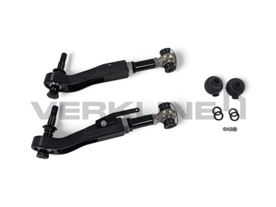
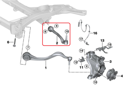
•2x Adjustable Caster Arms
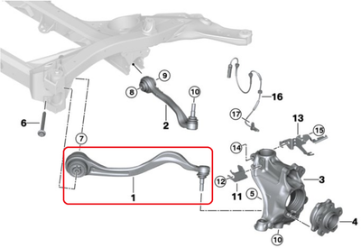
•2x Adjustable Camber Arms
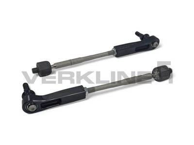
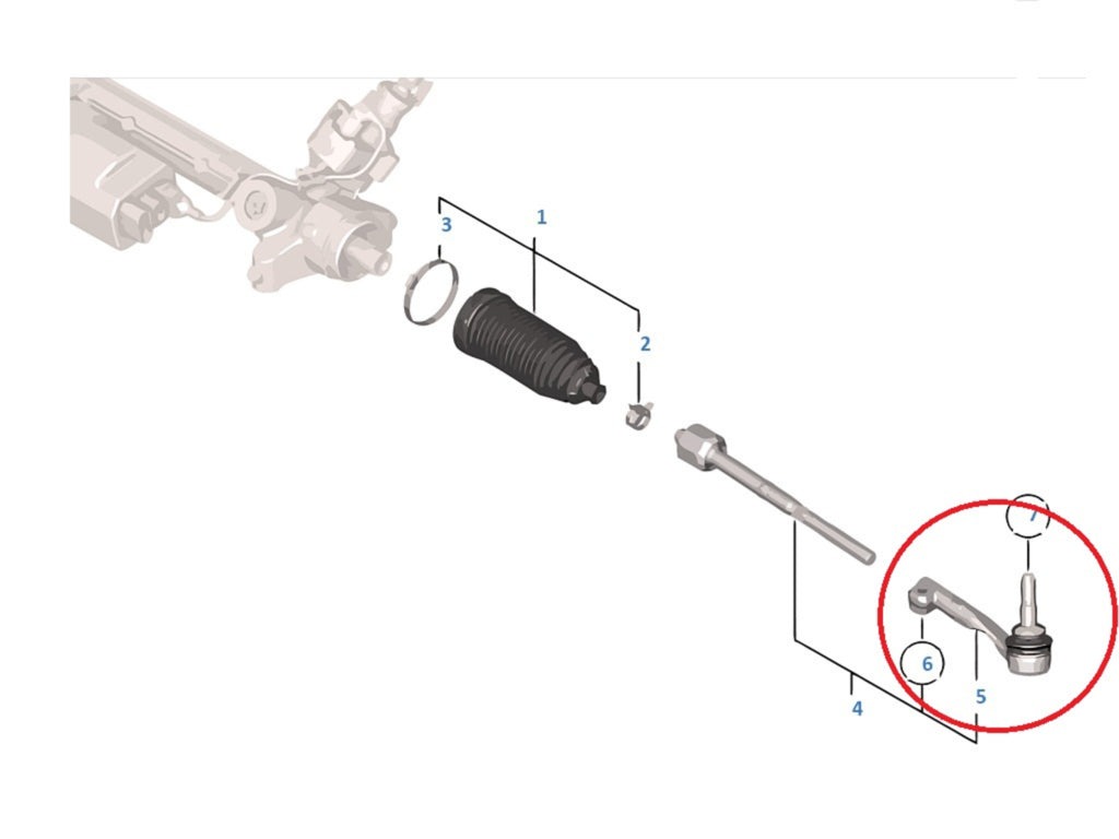
•2x Adjustable Tie Rod Ends (Bump Steer Corrected)
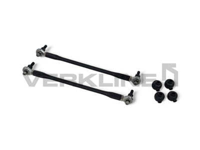
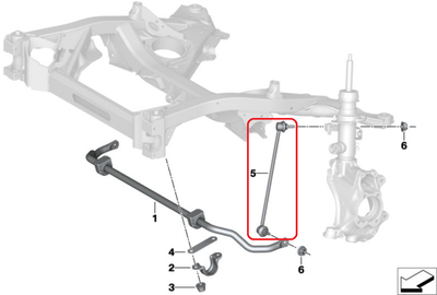
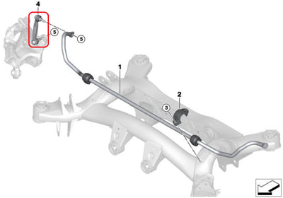
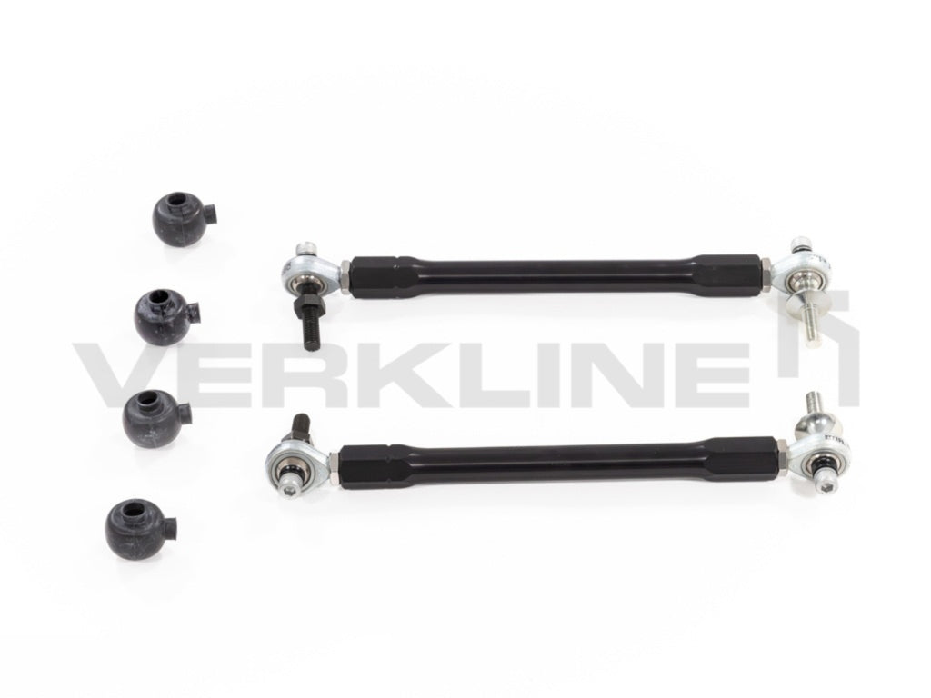
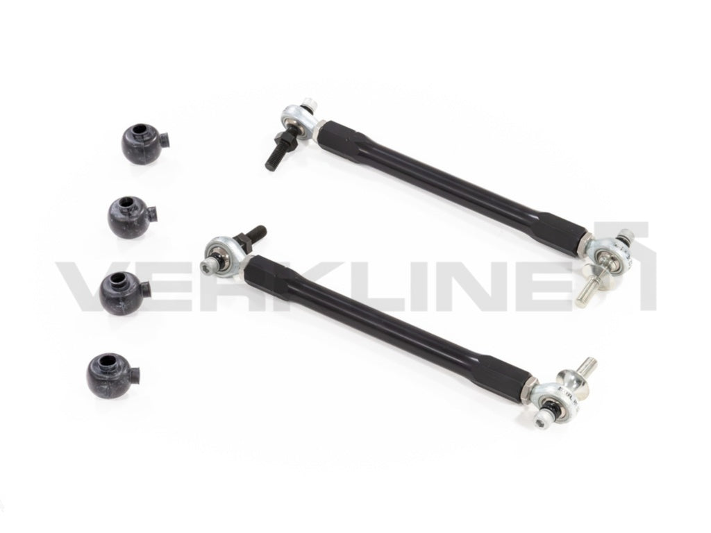
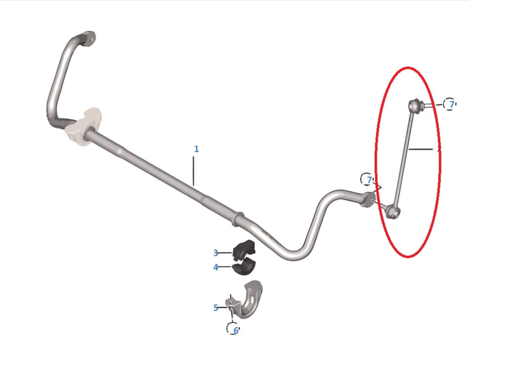
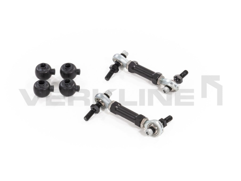
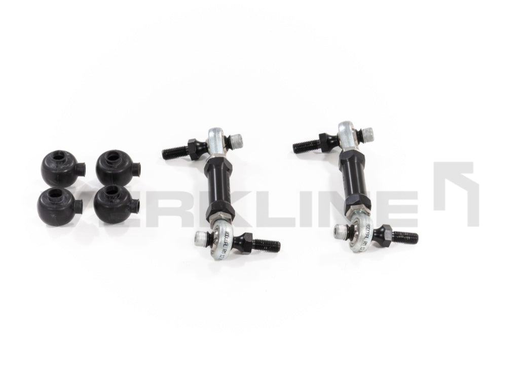
•2x Adjustable Anti-Roll Bar Drop Links
•4x Steering Rack Limiters (prevents tyre-to-arch contact at full lock when running wide wheels)
•1x Ride Height Sensor Bracket (retains OEM headlight levelling sensor - left side)
Rear Axle
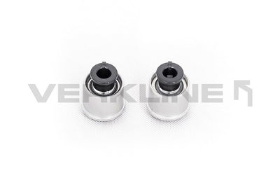
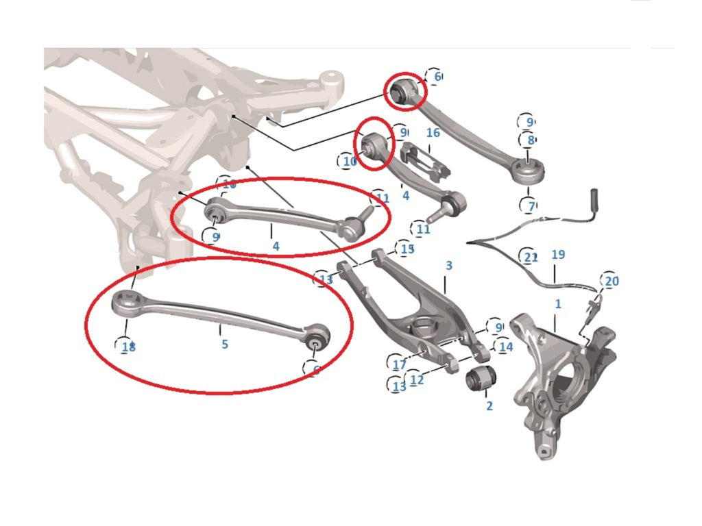
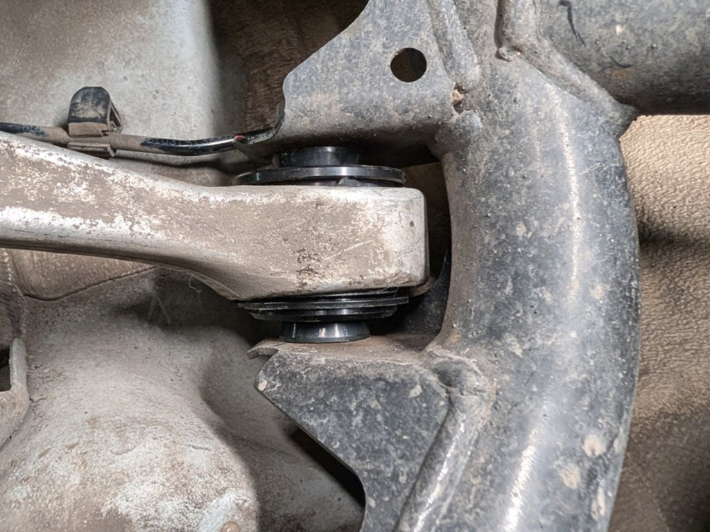
•4x Upper Arm Inserts (Retains OEM forged arm)
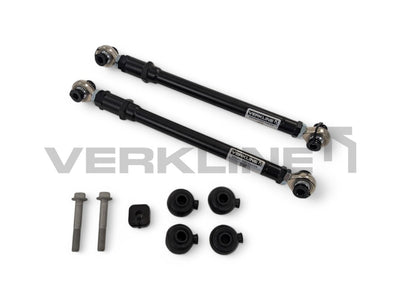
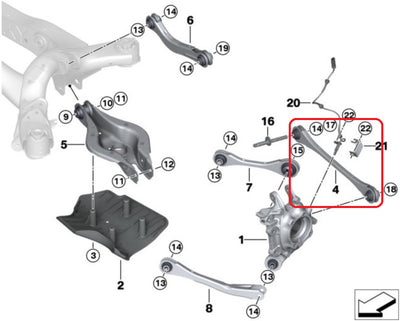
•2x Lower Adjustable Trailing Arms
•2x Adjustable Toe Links (Expanded range)
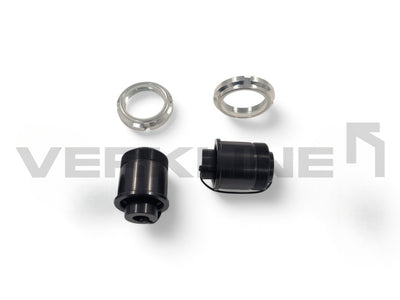
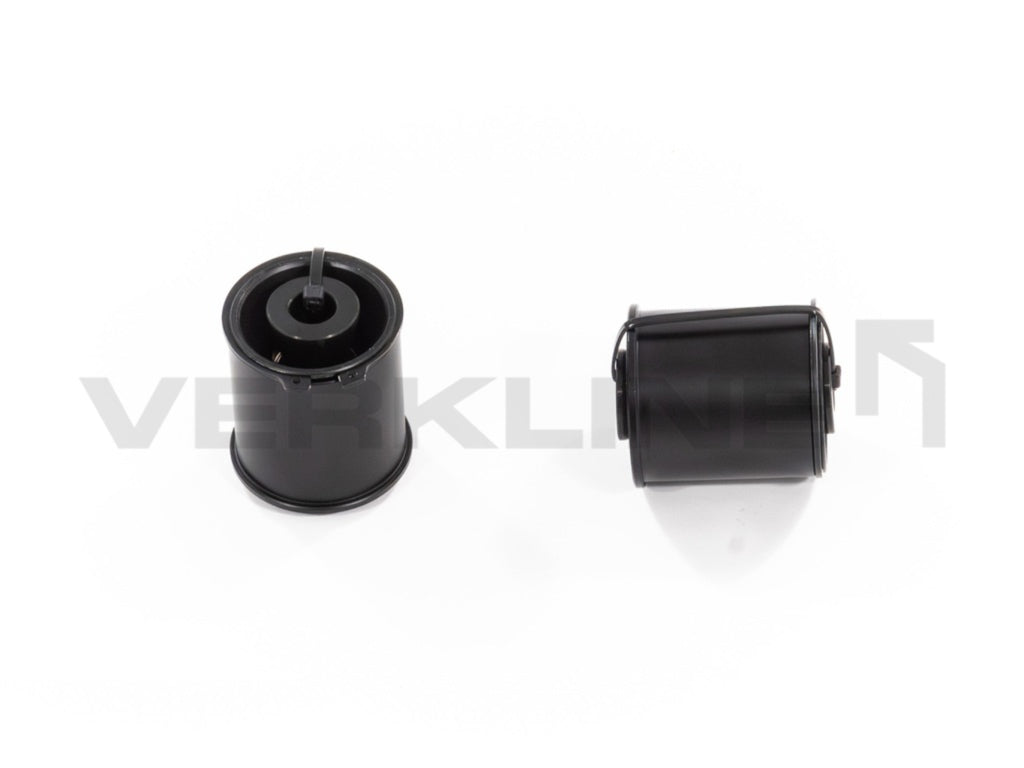
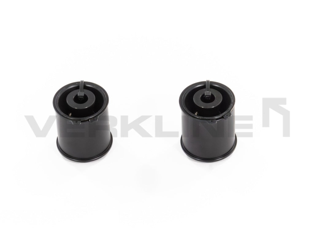
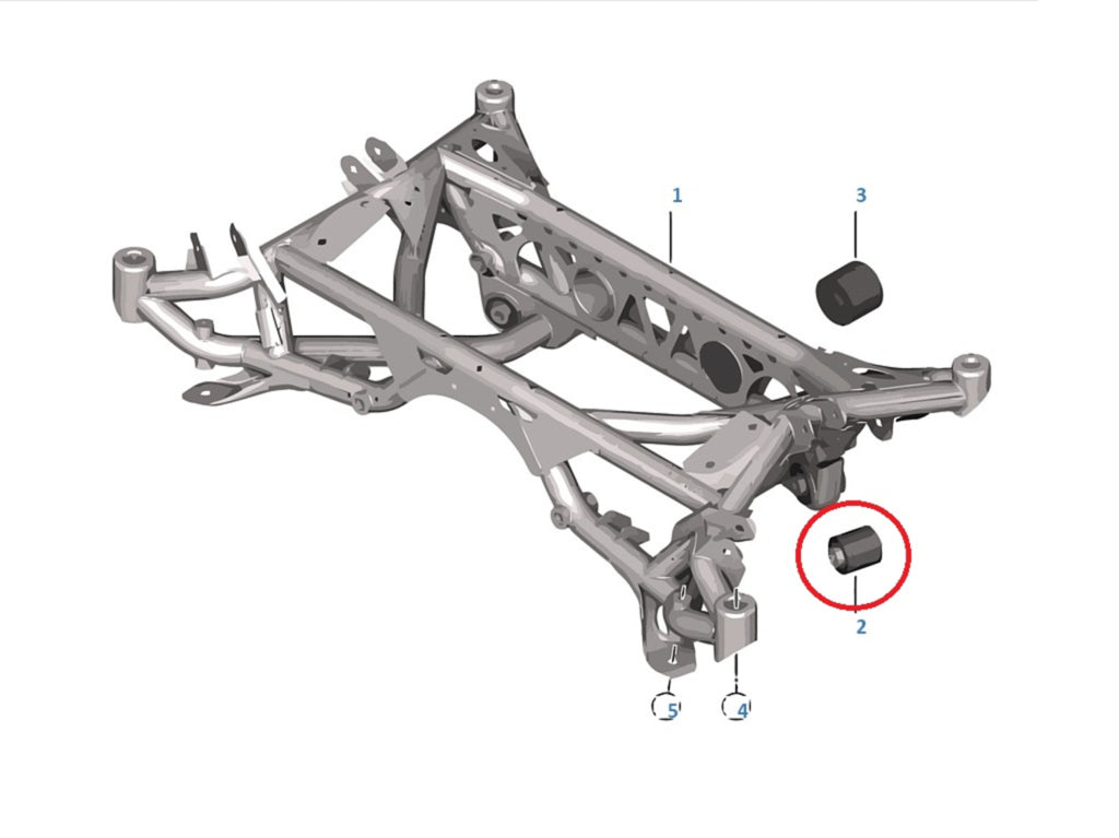
•2x Rear Subframe Inserts
•2x Adjustable Sway Bar Drop Links
Vehicle Compatibility
•BMW M2 (F87): 2015 - 2018
•BMW M2 Competition / CS (F87): 2018 - 2021
•BMW M3 (F80): 2014 - 2018
•BMW M4 (F82): 2014 - 2020
Compatible with common coilover platforms
The WAS-442 kit bolts to the factory F8x chassis pickup points and works with OEM dampers as well as every mainstream aftermarket coilover system. No coilover-specific adapters or brackets are required. Verified-compatible platforms include:
•OEM BMW F8x dampers (stock ride height)
•KW Variant 1 / V2 / V3 / V4 / Clubsport
•Ohlins Road & Track (R&T)
•Ohlins DFV / TTX
•Moton Clubsport / Motorsport
•JRZ RS Pro / RS Sport
•BC Racing BR / ER / ZR
•Fortune Auto 500 / 510 / Gen 8
•MCS TT1 / RR1 / RR2
•Tractive DDA / DDS
•AST 4100 / 5100 / 5200
•H&R Monotube / RSS
For wide-body builds using 10"-11" wheels the Stage 2 front subframe is required to relocate the coilover mounting position. Contact VERKLINE for platforms not listed above.
System Design Philosophy
Most kits are a collection of parts. VERKLINE is a system.
Every component was designed simultaneously in a single shared CAD model of the F8x chassis - so that bearing axes, adjustment ranges and clearances work together by design, not by luck.
This gives you two guarantees no mixed-parts setup can offer:
•Zero Interference: No collisions between parts across any suspension setup.
•Optimised Bearing Articulation: Every spherical bearing operates within its ideal range at any alignment setting.
See exactly what this means in practice - compare both scenarios below.
Engineering Philosophy: Beyond "Adjustability"
The VERKLINE Stage 1 kit is not simply a set of replacement arms; it is a comprehensive kinematic restoration of the BMW F8x chassis.
While the standard market approach is to copy OEM arms in aluminum and add a threaded adjuster, VERKLINE began with a full 3D scan of the F8x chassis - every suspension pivot point, every arm geometry, every clearance - and built a complete digital model of the car before a single component was designed. Over a 12-month development cycle with a team of engineers, we mapped the fundamental geometric compromises inherent in the factory road car: the non-linear bump steer curves, the camber loss during high-load cornering, the anti-dive behaviour that compounds at lower ride heights, and the coupling between camber and bump steer that makes the rear axle unpredictable at track camber values.
Every component was then validated through FEA (Finite Element Analysis) across 28 load scenarios - including combined cornering and braking forces, violent curb strikes and jump landing loads - before production. This is the same pre-production validation standard applied in professional motorsport engineering. It gives you the certainty that at the limit, nothing bends and nothing cracks.

Included Setup Documents
Every VERKLINE kit ships with a complete set of setup documentation developed specifically for the F8x chassis. This is not a generic alignment guide - it is a chassis-specific engineering document that covers arm lengths, shim positions, bump steer correction tables and recommended alignment targets for each use case.
Hand the document to your alignment shop. It contains everything they need to configure the car correctly from the first session - no guesswork, no phone calls to us. No other manufacturer for the F8x includes anything comparable.
→Front and rear camber targets
→Front caster targets
→Front and rear toe targets
→Ride height reference points
→Arm length presets (caster, camber, trailing, toe)
→Shim stack positions for bump steer correction
→Rear bump steer target value and setup tables
→Rear trailing arm length formula - calculate precise arm length for any combination of ride height, camber and bump steer target
→Notes for your alignment technician
The Complete Kinematic Ecosystem: Stage 1 + Stage 2
Every F8x geometry parameter sits in one of two categories. Category 1 parameters (camber, caster, toe, bump steer, front clearance, drop link angle) are controlled by the arms, tie rods and drop links - this is what the WAS-442 Stage 1 kit addresses completely. Category 2 parameters (front roll centre, rear roll centre, anti-dive geometry, chassis pickup point location, coilover mounting position) are controlled by the subframe and the uprights themselves, not by any arm. No arm kit from any manufacturer can reach Category 2 - the pickup points are physical features of the subframe and upright, and the only way to move them is to replace those components.
The WAS-442 (this kit) is the complete answer to Category 1. The VERKLINE Stage 2 kit - a rear tubular subframe and CNC-machined front uprights - is the complete answer to Category 2. Installed together, they are the only solution currently on the market that gives an F8x owner simultaneous control over every adjustable parameter in the suspension geometry. Stage 1 alone is a significant improvement on the factory setup, but it is not complete. Arms-only solutions from other manufacturers face the same ceiling.
Stage 1 and Stage 2 were designed as a single system from the first CAD iteration. Bolt patterns, clearances, bearing axes, and pickup point positions were all developed in one integrated model - which is why the transition from Stage 1 to Stage 2 does not require re-engineering, re-alignment, or any part change beyond the subframe and uprights themselves. Stage 1 customers are eligible for a 40% loyalty discount on Stage 2.
Stage 2 - Coming September 2026
Rear tubular subframe and CNC-machined front uprights. Both components were developed with a single goal - correcting the Category 2 geometry parameters (roll centre, anti-dive, pickup point position, coilover location) that arms alone cannot reach.
•Roll centre correction for better handling and agility
•Increased camber gain - better tyre wear and higher cornering grip
•Raised differential mounting position - reduced halfshaft angles, increased longevity
•Fully linearised rear bump steer curve
•Increased rear camber adjustment range without alignment loss under extreme loads
•20 mm roll centre correction
•Double-shear arm mounting points - lower compliance, sharper response
•Revised anti-dive geometry - higher grip on corner entry, easier trail braking, reduced wheel lockup risk
•Coilover relocation for 10"-11" wide wheel fitment
Stage 1 customers receive a 40% discount on Stage 2.
Front suspension 3D render
Who is this kit for?
The WAS-442 is engineered for F8x owners who want their alignment settings to actually reach the tyre - without rubber compliance, without guesswork, and without replacing individual arms one at a time. Three typical build profiles:
Profile 1
Weekend track-day driver
Lowered F8x on quality coilovers, 4-10 track days per year, runs stock or OEM-spec tyres. Wants a dialled, predictable chassis that does not change under load.
What the kit delivers: eliminates 100% of rubber compliance, sets consistent camber and caster, includes a Track setup document you hand straight to your alignment shop. Sealed preloaded MTE bearings hold alignment between sessions - no re-shimming, no re-alignment between track days.
Profile 2
Fast Road / lowered build
Lowered F8x on OEM or aftermarket coilovers, used for occasional canyon / mountain-pass runs and not set up as a dedicated track car. Wants a chassis that feels sharp under load without the extreme camber values of a circuit build. Sold as motorsport hardware - the owner chooses and takes responsibility for where it is used.
What the kit delivers: bracket retains OEM ride height sensor, maintenance-free sealed Getecno MTE bearings with AISI 316Ti stainless race and external dust boots (no seasonal maintenance, no salt-related play in climates with road salt and brake dust), Fast Road setup document with a lower-intensity alignment profile for lowered cars.
Profile 3
Time attack / competitive build
Dedicated track car, semi-slicks or slicks, aftermarket brakes, aero. Needs full geometry control including caster, maximum camber, bump steer tuning, plus the chassis-level parameters (roll centre, anti-dive, pickup point location) that arms alone cannot reach.
What the kit delivers: camber 2-5°, caster 6-10°, bump-steer-corrected tie rod, DIN 648K-compliant bearings rated 42 kN static load, and the complete kinematic path to Stage 2 subframe + CNC uprights (20 mm roll centre correction, 10"-11" wheel fitment, redesigned anti-dive geometry). Stage 1 + Stage 2 is the only complete solution on the market.
Technical FAQ
Q: Why is your front Caster Arm a CNC-milled billet part instead of a straight tube?
The WAS-450 caster arm uses a CNC-milled profile shaped directly around a full 3D CAD assembly of the F8x suspension. This gives three structural guarantees no straight rod can provide:
•Guaranteed clearance: The milled shape routes the arm body away from the tie rod across every alignment setting we offer - verified in CAD for every combination of ride height, camber (2°-5°) and caster (6°-10°).
•Optimised bearing axis: The bearing housing is angled at 4° to keep the spherical bearing within its articulation range across full suspension travel. A straight rod forces the bearing inline with the rod axis - the angle BMW engineered for a rubber bushing, not for a spherical bearing.
•Structural integrity without compromise: The stud length is kept at OEM specification. Some competitors increase stud length to add anti-dive adjustment - on an F8x that already runs 60-70% anti-dive when lowered, this makes handling worse, not better. We leave the stud at standard length and keep the full pin cross-section for maximum strength.
Q: Can I adjust caster and camber independently? How is that different from stock?
With the VERKLINE kit, the caster arm (WAS-450) and camber arm (WAS-451) are two separate, independently adjustable billet arms. You can set caster anywhere between 6° and 10° without touching the camber setting, and set camber between 2° and 5° without affecting caster.
This matters practically because the optimal caster for steering feel and high-speed stability is not the same number as the optimal camber for maximising front grip in corners. With OEM arms you have no choice. With VERKLINE you dial both separately for your specific use case - fast road, track day, or circuit.
Q: Why did you design a fully CNC-milled caster arm instead of making an insert for the OEM arm like some competitors?
The VERKLINE caster arm is a ground-up CNC-milled billet design for three reasons no insert can address:
•Collision clearance: A straight or OEM-geometry arm creates a real risk of contact between the caster arm and the steering tie rod at certain suspension travel and steering combinations. Our milled shape was designed around a full 3D CAD assembly of the F8x to guarantee clearance at every alignment setting we offer.
•Bearing axis optimisation: The bearing housing in our arm is tilted at a calculated angle to keep the spherical bearing within its articulation range across the full suspension travel. An insert inherits the OEM housing angle - designed for a rubber bushing, not a spherical bearing.
•Adjustability: The milled design accommodates our threaded adjuster sleeve, giving ±22 mm of length adjustment. An OEM insert has no adjustment - it preserves the stock pivot point exactly.
Q: What does the rear kit actually fix - and why can't I just adjust camber with the OEM bolts?
The graph below shows what happens to rear toe angle through suspension travel on the OEM setup at different camber values. At -1.5° the curve is relatively flat. At -2.5° and -3° - which are normal track day values - the curve becomes dramatically non-linear. The toe variation nearly triples, meaning the car is actively steering itself as the suspension moves under braking and cornering loads.


No other manufacturer for the F8x addresses rear bump steer linearisation. Others offer adjustability - VERKLINE offers linearisation. The difference is not how far you can move the toe setting - it is whether the car behaves predictably at every point in suspension travel, at every camber value you run.
Q: How does lowering the vehicle and adjusting camber impact suspension kinematics?


Q: Does the Stage 1 kit include front roll centre correction? How much does it lower the camber arm compared to stock?
On the camber arm - which sees peak loads exceeding 23 kN - even a modest amount of roll centre correction would require compromising either pin strength or bearing articulation range. We chose not to make that compromise. The tie rod end is a different case. Because it operates under approximately four times lower loads than the camber arm, we were able to introduce a shim stack on its pin. This is why bump steer adjustment is possible on the WAS-452 tie rod end: the same OEM upright hole diameter accommodates a sufficiently strong and long pin without structural risk.
The correct solution for front roll centre correction is a redesigned upright - not a longer arm pin. This is exactly what our Stage 2 upright addresses: 20mm of roll centre correction, double-shear arm mounting points for maximum rigidity and minimum compliance, and a relocated coilover position to accommodate 10"-11" wide wheels. The correction limit of 20mm was set by the inner diameter of 18" wheels.
In the meantime, Stage 1 already delivers a significant handling improvement on lowered F8x cars - not through roll centre correction, but by eliminating 100% of rubber compliance from the kinematic chain. On a car with OEM bushings, the geometry deflects under load regardless of how it is set up statically. Once every pivot point is a spherical bearing, your alignment settings are what actually reaches the tyre contact patch.
Stage 2 uprights are currently in development. Stage 1 customers are eligible for a 40% discount on Stage 2.
Q: Why do you use inserts for the Rear Upper Arms instead of replacing them with adjustable arms?
In the F8x five-link rear suspension, camber is a function of the lower trailing arm and toe link geometry. The correct lever for adjusting rear camber is the lower trailing arm length - which is why VERKLINE supplies a fully adjustable trailing arm. Changing the length of the upper lateral arm simultaneously affects camber, camber gain and suspension kinematics in ways that are difficult for alignment technicians to compensate for. The result is a setup that is harder to dial in and harder to reproduce session to session.
There is also a practical geometry problem: adjusting camber via the upper arm moves the tyre contact patch inward toward the wheel arch. With any combination of wheel width, offset and ride height, this creates a risk of tyre-to-arch contact during suspension travel that the manufacturer cannot eliminate for all customers. VERKLINE avoids this by adjusting camber at the lower trailing arm, which moves the wheel outward in the arch - widening the track and reducing lateral load transfer, rather than creating a clearance problem.
The OEM BMW rear upper arm is an exceptionally high-quality forged component - lightweight, strong, and geometrically correct for this suspension. The only flaw is the rubber bushing, which deflects under load and blurs the geometry regardless of how precisely it was set statically. We replace the bushing with a spherical bearing insert and retain everything else. The result is a system that is fully adjustable where adjustment matters, and unchanged where OEM is correct - without adding unnecessary complexity to the alignment process.
Q: Can the WAS-442 be used outside of a circuit environment?
Mechanically, the kit is compatible with OEM coilovers and standard ride heights. Every pivot uses a maintenance-free sealed Getecno MTE bearing (no grease, no oil, no periodic servicing). The camber arm (WAS-451) includes a dedicated bracket that retains the OEM ride height sensor on the left side, preserving the headlight levelling system with no error codes - a detail no competitor addresses.
Every kit ships with two setup documents. The Fast Road document provides a lower-intensity alignment profile (comfort-biased camber, caster and toe targets, ride height reference, bump steer correction) for lowered cars where track-pace camber is not required. The Track document provides aggressive alignment targets for semi-slick and circuit tyres. The customer and their alignment technician select the profile appropriate for the car's intended use.
Q: Does this kit fix the handling issues on lowered cars?
Q: What alignment do I need after installation?
After the initial setup, further adjustments do not require a workshop visit. Because all VERKLINE arms are adjusted externally with the wheels on the ground, camber and toe can be changed while the car is standing on its wheels with alignment heads in place - on a standard 4-post lift, a garage floor, or directly in the pit lane using the string method. You do not need to disassemble the suspension to make a geometry change. This is how the kit was designed: so that adjustments between sessions are fast, repeatable and do not require another trip to an alignment shop.
Q: Why are Steering Rack Limiters included, and when do I need them?
The WAS-450 caster arm uses a CNC-milled profile that routes around the tie rod - the geometry that eliminates tie-rod collision risk. That profile places the arm body slightly closer to the wheel than a straight-rod design. At full steering lock with very wide wheels (around 10"), the tyre can contact the caster arm in certain setups.
This is not a problem unique to VERKLINE. All caster arm designs - including every straight-rod design currently on the market - face the same fundamental geometry: the F8x double-wishbone places the caster arm and tyre in close proximity at full lock. Manufacturers of straight-rod caster arms explicitly warn customers in their fitting instructions to check for tyre-to-arm clearance across the full suspension travel and full steering lock after installation. They identify the risk and leave the solution to you. We ship the solution.
The limiters are small spacers that install on the steering rack shaft, reducing maximum rack travel by 6 mm per side each. In most setups - standard-width wheels, or moderate ride height reduction - one spacer per side is sufficient, or none are needed at all. Two per side covers the most aggressive combinations of very wide wheels and low ride height.
Installing them takes around 20 minutes: remove the steering rack boot, unscrew the inner tie rod, fit the spacer on the rack shaft, reassemble. Full instructions are included. Always use the same number of spacers on both sides of the rack.
Q: Why use a camber arm instead of camber plates?
Camber plates work at the top of the strut: they tilt the wheel inward at the top, moving the contact patch inward and narrowing the track width. A narrower track means more lateral load transfer under cornering - which is the opposite of what you want for grip. Camber plates also increase the bending load on the OEM strut and bearing, since the strut now operates at an angle it was not designed for. And because most camber plate designs couple camber with caster, adding negative camber simultaneously reduces positive caster - a geometry trade-off you cannot independently control.
The VERKLINE camber arm (WAS-451) operates at the lower wishbone. Adding negative camber via a lower arm simultaneously moves the wheel outward in the arch, widening the track. A wider track reduces lateral load transfer - meaning more grip from each tyre, not just more camber angle. The structural load is carried by the dedicated billet arm rated to 23.2 kN peak load, not by the OEM strut. And because caster is controlled by a completely separate arm (WAS-450), camber and caster are fully independent - you set each to its optimum without compromise.
Camber plates are a practical solution for cars without a lower camber arm. On the F8x, the geometry exists to do it properly.
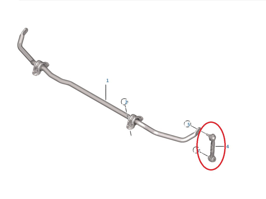
Q: Why do the anti-roll bar drop links matter on a lowered car?
In the OEM configuration at stock ride height, the drop link sits close to vertical and the anti-roll bar is in its neutral, unloaded position. Lower the car, and the drop link angle changes: the bar is now pre-loaded even when the car is sitting statically on flat ground. Pre-loading an anti-roll bar means it is no longer working symmetrically left-to-right - one side is already partially compressed before any body roll occurs. The result is unpredictable and inconsistent cornering balance.
An adjustable drop link allows you to restore the neutral anti-roll bar position at your actual ride height, so the bar begins working from zero load in both directions simultaneously. The VERKLINE WAS-453 drop link was designed with a verified ±30° articulation range across the full suspension travel and steering range - measured directly in the F8x CAD model across the complete operating envelope of ride height and steering angle. This ensures the spherical bearings never reach their articulation limit, which would cause binding and unpredictable load spikes in the anti-roll bar system.
Q: How does the WAS-452 tie rod end correct bump steer, and how is it different from just adjusting tie rod length?
On the F8x front suspension, bump steer is primarily caused by the vertical position of the outer tie rod end relative to the steering axis. If the tie rod end is too low or too high relative to where it needs to be for the current ride height and caster setting, the toe angle changes as the suspension travels - this is bump steer.
Adjusting tie rod length (the thread adjuster in the middle of the rod) changes the toe angle - useful, but it does not correct the vertical position of the outer end, which is what determines the bump steer curve shape. The WAS-452 uses a stack of precision shim rings between the spherical spacer and the upright pin. Adding or removing shims raises or lowers the outer end of the tie rod at the upright, directly correcting the bump steer curve without affecting toe. This means you can set toe and bump steer independently - something not possible with a length-adjustable-only tie rod end.
The included setup document specifies the correct shim configuration for each combination of ride height and caster setting, so your alignment technician can execute the correct bump steer correction from the first session without needing a dedicated bump steer measurement rig.
Q: Is there a ride height below which the kit can no longer fully correct the geometry?
The VERKLINE Stage 1 system is optimised for a ride height of approximately 60-90 mm, measured from the wheel arch lip to the upper edge of a 19-inch rim. Within this range, the rear trailing arm covers all practical combinations of camber and bump steer simultaneously, and the setup document provides exact arm length presets and a calculation formula for any combination within this window.
Below approximately 60 mm, the geometry hits a wall that is built into the car - not into our parts. Two things happen that no arm kit can fix, regardless of manufacturer:
1. The rear trailing arm runs out of useful adjustment range. As ride height decreases, the arm length required to maintain correct geometry increases. At extreme combinations of low ride height, high camber and a specific bump steer target, the arm reaches the boundary of its physical adjustment range - it is no longer possible to achieve all three parameters simultaneously. This is not a VERKLINE design limitation; it is a consequence of where BMW placed the chassis pickup points.
2. Roll centre drop and anti-dive increase cannot be corrected by arms alone. These are functions of the chassis pickup point positions - fixed points in the body structure. No matter how precisely an arm is manufactured or adjusted, it cannot move its own mounting points. Correcting roll centre and anti-dive geometry at extreme ride heights requires physically relocating those mounting points - which means a redesigned rear subframe and front upright. This is exactly what Stage 2 addresses.
Running the car below 60 mm is not wrong - many drivers do it and it lowers the centre of gravity, which has real benefits. But beyond this point, the geometry compromises that accumulate are structural, not parametric. They cannot be dialled out with any combination of arm lengths, regardless of which brand's kit you install. Stage 2 was designed specifically to extend this boundary by physically relocating the suspension pickup points - on the rear tubular subframe and on the CNC-machined front uprights. This is the only approach that actually moves the kinematic pivot geometry rather than working around it. No other manufacturer for the F8x currently offers this.
Q: Why do sealed preloaded bearings matter more than standard PTFE-lined rod ends?
A standard PTFE-lined motorsport rod end runs PTFE as a surface liner bonded to the race. The liner is thin, wears as the ball articulates under load, and is eventually worn away. Once the liner is gone, the ball contacts the race directly - the joint develops measurable play, steering response softens, damper load transfer becomes less predictable, and alignment drifts. Open rod ends of this type also have no dust seal, so road salt and brake dust accelerate the wear further.
The Getecno MTE used in the WAS-442 is a fundamentally different design. First, the PTFE is not a liner - it is integrated into a bronze wire mesh matrix pressed into the race. The bronze mesh carries structural load; the PTFE reduces friction; the two wear as a single composite surface, not as two separate layers with a sacrificial top. Second, the ball-to-race coupling is preloaded at zero clearance at the factory - the joint has no play on day one, not just after break-in. Third, the housing is sealed, and every pivot ships with an additional external dust boot. The operational consequence on the car: alignment settings, steering response and damper behaviour are the same in month 1 and month 24. You do not need to re-shim the joints between track days. In climates with road salt and brake dust exposure, there is no salt-related play to develop over winter seasons.
This is why VERKLINE publishes bearing-level specifications (tier MTE, body 42CrMo4, race AISI 316Ti, ball 100Cr6, DIN 648K compliant, 42 kN static load) and competitors in the arms-only space generally do not. When the bearing is a sealed preloaded motorsport-grade component, the specification is a differentiator. When it is a generic PTFE-lined rod end, there is little useful specification to publish.
Q: How does this compare to Chinese-manufactured kits?
Specifications
| Product identity | |
| SKU | WAS-442 |
| Product type | Fully adjustable wishbone kit, Track Package - Stage 1 |
| Vehicle platform | BMW M2 F87 (2015-2021), BMW M3 F80 (2014-2018), BMW M4 F82 (2014-2020) |
| Axles covered | Front and rear, single shared CAD model |
| Total piece count | 22 pieces (complete both-axle kit) |
| Adjustment ranges | |
| Front camber | 2° to 5° (continuously adjustable) |
| Front caster | 6° to 10° (independent of camber) |
| Toe | Front and rear, fully adjustable |
| Bump steer | Corrected front and rear (shim-adjustable front tie rod) |
| Materials & manufacturing | |
| Control arm material | AW-6082 T6 aluminium billet, CNC-machined |
| Pin material | 42CrMo4+QT alloy steel (quenched & tempered, > 750 MPa yield) |
| Bearing tier | Getecno MTE - top series in the Rodobal (Italy) catalogue |
| Bearing body material | 42CrMo4 quenched & tempered steel (same grade as pivot pins) |
| Bearing race material | AISI 316Ti stainless steel (corrosion-resistant, salt-environment grade) |
| Bearing ball | 100Cr6 hardened, ground, thick chrome plating |
| Anti-friction insert | PTFE integrated in bronze wire mesh matrix (not a surface liner) |
| Bearing coupling | Preloaded zero-clearance, sealed housing |
| Bearing compliance | DIN 648K (forms A & J), ISO-DIN 13-6h thread class |
| Static radial load per bearing | 42 kN (4,200 daN, RM 12 MTE series) |
| Dust protection | Three-layer: sealed bearing housing + closed arm geometry + external rubber dust boot (factory-fitted) |
| Maintenance | Self-lubricating, maintenance-free (no greasing, no periodic service, no re-shimming) |
| Engineering validation | |
| FEA scope | Every load-bearing component, 28 load scenarios |
| Peak validated load | > 23 kN on camber arm (worst-case scenario) |
| Caster arm design | CNC-milled billet profile with 4° bearing axis, tie-rod clearance verified across full adjustment range |
| Compatibility & use | |
| Coilover compatibility | OEM dampers and all mainstream aftermarket platforms (KW, Ohlins, Moton, JRZ, BC Racing, Fortune Auto, MCS, AST, H&R) |
| OEM ride height sensor | Retained via integrated bracket on WAS-451 camber arm |
| Included documentation | Printed Fast Road setup and Track setup sheets (F8x-specific) |
| Ecosystem position | Stage 1 (arms, tie rods, drop links) - covers Category 1 parameters: camber, caster, toe, bump steer, clearance, drop link angle |
| Stage 2 upgrade path | Rear tubular subframe + CNC front uprights - covers Category 2 parameters: roll centre, anti-dive, pickup point position, coilover location. 40% loyalty discount for Stage 1 owners. Stage 1 + Stage 2 = only complete F8x kinematic solution on the market. |
SKU: WAS-442 · Last technical update: April 2026
CNC Precision
Milled from solid aluminum or steel
2 Years Warranty
Full manufacturer warranty
Shipping within 24 hours
From our warehouse if item is in stock
Made in Poland
Designed and manufactured in Poland (Europe)